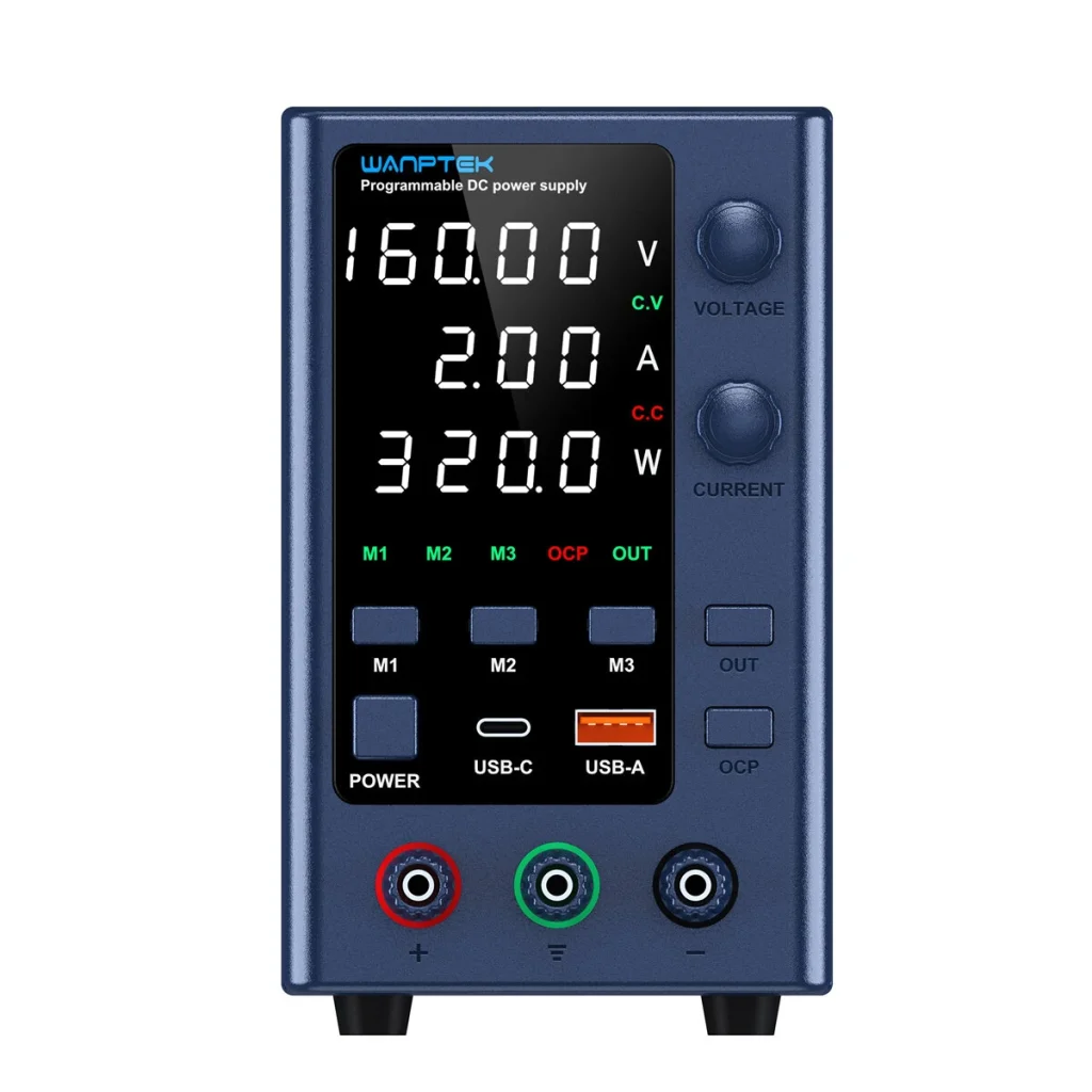
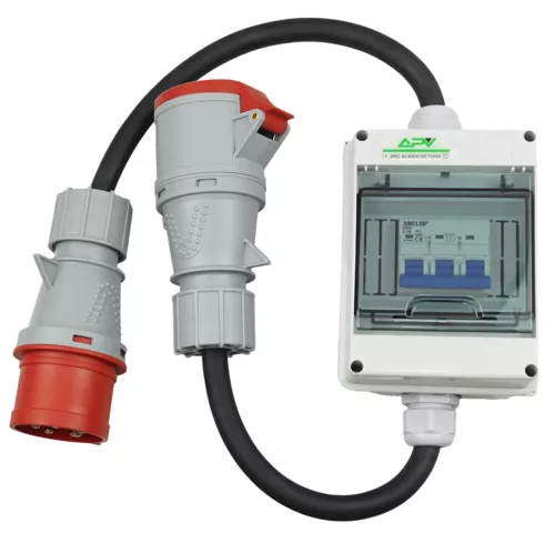
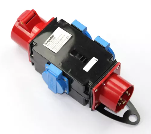
We use test stand which simulates grid connection, main switch, regular loads, critical loads and a string of panels.
Power supply 160V, 2A max.

3 phase cable and switch
the cable on the output side is dismantled so that current sensors of the energy meter can be attched easily.

2 AC splitters, one for regular loads, the other oe for critical loads

Diagram
 AC 380 from grid
          |
          +-------------------------------------------+
          |                                           |
   3 phase switch                                     |
          |                                           |
      /   |   \    I===================I              |
     |    |    |...I energy meter with I              |
     |    |    |...I sensors wrapped   I              |
     |    |    |...I around each phase I              |
      \   |   /    I===================I              |
          |                                           |
   AC splitter  --------------------- regular loads   |
          |                                           |
          |                                           |
I=========|=======================I                   |
I         |                       I                   |
I    backup box --------------------- critical loads  |
I         |                       I                   |
I     inverter  ------ battery    I                   |
I         ^     \                 I                   |
I         :      --- wifi stick   I                   |
I         :                       I                   |
I         :           LAN Box <-----------------------+
I         :               |       I                   |
I=========================|=======I                   |
          :               |                           |
          :           WIFI LAN Bridge <---------------+
          :                                           |
   DC power supply <----------------------------------+
The components inside the === double lines === are the system under test.
The other parts belong to the testing equipment.