This page explains the steps needed to make the initial configuration for a ES-Micro system. Normally this will be done before you receive the equipment.
Test environment needed
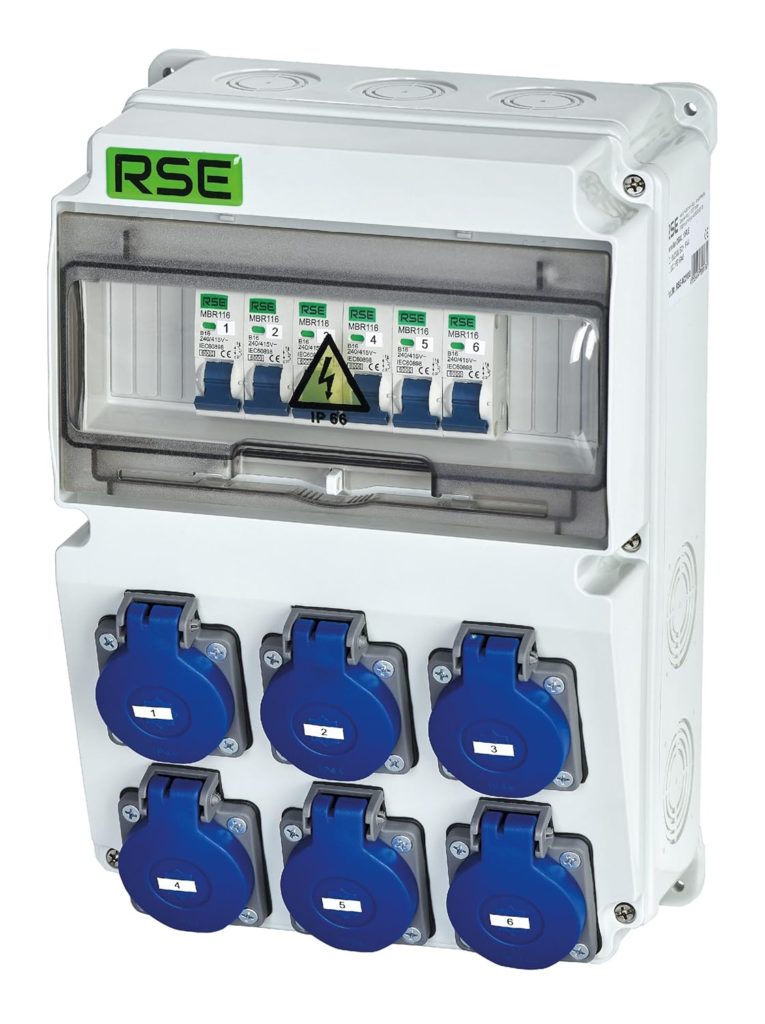
FIrst, we must have a specially configured CSSB with free slots to install the counter (Shelly 3EM) if needed. Some of the AC 220 sockets will be used to connect a micro inverter (one at at time), the others will be used to simulate the consumption of a house (regular loads, critical loads).
A laboratory charger (30V, 10A) with the ability to regulate voltage and to limit current will be used to feed DC energy into the micro inverters (one after the other).
The AC side of the micro inverter is connected to a plug in the CSSB via a Switch. This allows us to connect/disconnect the AC side of the inverter easily.
A small resistor between the DC power supply and the inverter is used to simulate the behavior of a solar panel. This means that the voltage will go down a little bit if the inverter draws more current. The charger delivers 30V, the resistor has 3 Ohms.If we want to have 5A at 25V and
A lamp (20W) is connected to another pug of the same phase via another switch. A second lamp is connected to a different phase. This allows us to simulate changing loads.
The “system under test” (i.e. the system to be configured and delivered) consists of the micro inverters, the Victron Multiplus and the battery and the shelly3EM
… <NOTE: The description is not yet complete …
