PV wires (photo voltsic wires) carry the direct current (DC) generated by the solar panels to the inverter. Grounding wires provide a safety function by connecting metal frames and other parts of your solar system to the ground. This reduces the risk of electrical shock or fire in the event of a fault or power surge.
Grounding wires
Grounding wires are green/yellow and should have a diameter of 6mm² or more. If you decide to connect the frames of your panels or the mounting construction to a lightning protection system (which normally is not needed) at least 16mm² copper wires are required.
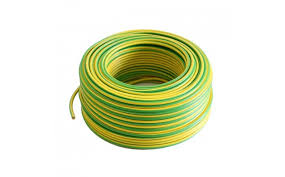
Connect the grounding wire to the metal frame of the solar panels and run it to a ground rod or other grounding system. Depending on the legal situation in your country you may have to install grounding wires or not. They are useful means of protection anyway.
Normally you are not required to connect the metal parts of your solar system to an existing lightning protection system. Instead you should keep a safe distance (0.5 – 1m) between all metal parts of your system and any part belonging to a lightning protection system.
PV wires
Modern panels produce ~43V at ~10A in their maximum power point. The diameter of the cable attached to the panel is 4mm².
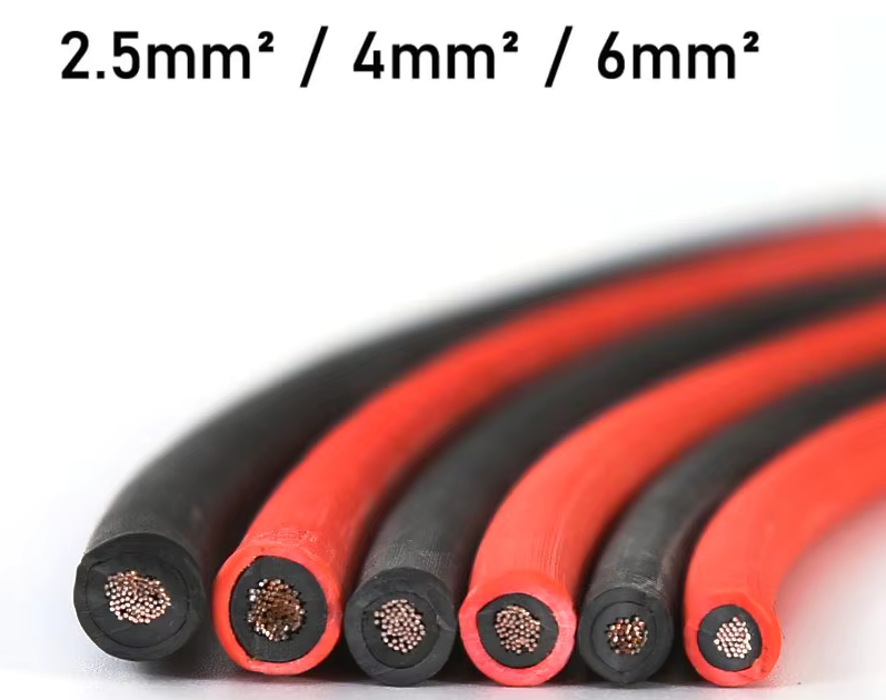
If you have to extend DC cables in an ES-Micro system 4mm² will always be fine.
If you link panels in series (ES-Hybrid systems) you need to calculate the necessary diameter for the long DC cables which connect the string array to your inverter. Thin cables produce more loss but are cheaper than thicker cables. Assuming that you have a string with a maximum of 16 panels a diameter of 4mm² will be ok if you have less than 30m of distance between the inverter and the panels. You can check this, if you enter 16×43=688V and 10A and 2*30m=60m into the calculator linked below.
https://www.solar-wind.co.uk/info/dc-cable-wire-sizing-tool-low-voltage-drop-calculator
You should choose a red cable for positive and a black one for negative polarity. A single cable will always have two different types of MC4-connectors (male [-] and female [+]) at its ends. This means that a red (positive) cable will have a female connector [+] and a male connector [-]. You plug its male side into the positive end of your panel string (which is the thin long piece usually carrying a thin red ring) and then its other end (the female plug) become the plus side of the string – which you will connect to the inverter.
Fixing connectors to cables
You must buy the necessary length of cables and some connectors. You need a special tool for crimping the cables. Look at the video. Do NOT try to crimp wires without the special crimper tool. You will produce bad connections which probably will produce problems later when operating at full load.
How to connect DC cables
Connecting cables to panels is the last step after the panels have been properly mounted. Sometimes it is possible to make all connections after all panels have been mounted. But usually you mount a panel and then connect it immediately to its predecessor in the string (or to its micro inverter in the case of an ES-Micro system). You should have a painted sketch which clearly shows how panels are arranged physically and electrically. Keep this plan even after your system is working. It may be useful if something fails some day. It is a good idea to fix the cables to the mounting construction with cable ties.
Connecting panels to micro inverters can be done at any moment without special care. The rest of this chapter deals with string arrays used in ES-Hybrid systems.
Arranging Panels in Strings
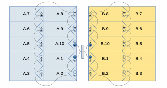
Here is a very simple example for a panel connection plan.
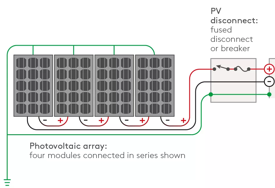
Connecting panels to a string means, that at the two ends of the growing string you will instantly have the sum of the idle voltages of the connected panels (if there is sunlight).
The next diagram shows two strings, 10 panels (group A) facing West and the other one with 10 panels (B) facing East. The connections are made in a way which allows to connect the four cables leading to the inverter at a central point. 10 modern panels (440Wp) will produce ~500V idle voltage during sunlight.
Check the path which will lead from the panels to the inverter. This could be an unused channel of a chimney if panels are mounted on a roof.
Suggested sequence of worksteps
First cut cables roughly to the necessary length. You will then have two black and two red cables of similar length. They may differ a little bit because the ends on the roof will later go to the first and to the last panel of each string.
Now mark a red and a black cable with a blue tape at both ends and mark the other pair of cables in the same way with a yellow tape. Place your color marks at least 20 cm away from the ends of the cables so that they do not get lost when you will fix the connectors.
Then tie the four cables together with some adhesive tape at one end; place the adhesive tape directly at the end and another ring of tape one meter away. Now you have a stable bundle of four wires, two red and two black ones. From the roof you lower this bundle down into the chimney until it will arrive at the basement floor (or wherever your inverter and battery are placed).
You pull the bundle out of the chimney until it is close enough to the inverter to be connected comfortably (not being too mean with cable length ..) Now you untie the bundle and connect two MC4 plugs with a male pin to the black cables and two sockets with a female pin to the red cables. Make sure that your color markings (blue and yellow tape) are not removed during the crimping process.
Now put a plastic bag around the two black plugs and another one around the two red MC4 sockets – making sure that no one will touch them while you are on the roof.
Go back to the roof and bring the other ends of your cable pairs into position. Fix the cables as needed, for example with cable ties. Shorten the cables if you want, but make sure you can easily connect them to the correct cable end of their associated panel.
Then crimp MC4 connectors to the cable ends. This time you use male plugs for the red cables and female sockets for the black cables.
Then start to mount and connect panels beginning with the first panel of the first string, linking all panels which face into the same direction according to your plan. Do not connect more than 16 panels to a string. Finally mount the last panel and connect the red wire (the one with the same color mark as your initial black wire) going to the inverter.
Repeat the same procedure with the second group of panels.
The final step should be done when there is no sun, i.e. early morning or late evening. You remove the plastic bags and connect the cable pairs to the corresponding inverter inlets. The color code helps you to find the correct connection points. It does not matter whether “blue” or “yellow” will be associated to #1. But you should note the colors on your plan.