We use a test stand which provides three phase grid connection, a main switch, a built-in energy meter, some regular loads, some critical loads and a DC supply to simulate solar panels.
Server communication
Growatt inverters can use a WIFI stick to communicate with the router at the target location. Once connected the router will contact the Growatt server for monitoring on request of the inverter. This mode of communication means that the WIFI stick must be set up to connect to the customer´s WIFI access point – which cannot be done easily in advance. ALso, if the customer changed the WIFI password, the solar system would no longer be able to pass data to the monitoring server.
Therefore ES-Hybrid Systems use a different way of communication. They come with a SHINE Link RF Stick and a Shine LAN Box. The LAN Box must be connected to the Web router at the target location via a (short) network cable. The advantage is that the wireless communication between the inverter dongle(s) an the LAN box is encapsulated. No passwords are needed. The communication is more robust and it is easier to add inverters to an existing plant. A LAN box can handle up to eight RF sticks.
It is important to understand that the RF stick itself must not be registered as a data logger at the server. Instead it passes its ID and its datat through the LAN box to the Growatt server platform. This means that the LAN Box must be registered as the (sole) data logger for the plant.
Details of installation are explained in the video:
An ES-Hybrid system can work without any communication to the monitoring platform. You can do all the preparation work offline. But if you want to see what is going on without watching the instruments of the DC supplies and without a clamp current meter you need a Shine LAN Box connected to your LAN and paired with the inverter dingle as descirbed in the video.
Simulation of panels
Two power supplies 160V, 2A
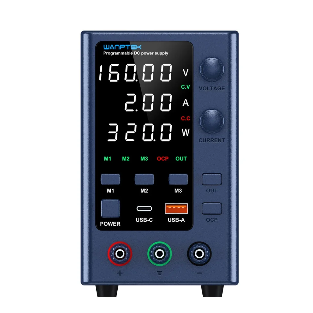
The power supplies are connected in series with a small resistor (2.4 Ohms) in series. We are limiting the current to 1.80 A on one power supply and 1.81 A on the other one. Voltage is set to 150 V on each of them. OCP must be disabled on both power supplies.
The resistor consumes 4V / 7W at 1.8A It helps the inverter to stabilize the amount of energy it tries to draw from its DC input. Initially the inverter takes the full voltage of 300V and starts with a very low current; then its power point tracking algorithm will draw more and more current. Because the resistor takes a small amount of the voltage away the PPT tracker will observe a slight decrease of ots input voltage – just as it would happen with real solar panels.
As soon as the current approaches 1.80A the first power supply will lower its output voltage to keep the current at/below 1.80A. If the current is above 1.81A the second one will do the same. The inverter might overshoot that point. It then will notice that as an even more drastic declie in input voltage because the second power suplly also enters its delimiting region.
The specs say that the inverter needs 140V at minimum. So theoretically it would be possible to use one power supply only. But we observed some situations where the inverter broke down completely when it only had 160V as a starting point.
Experience has shown that with 300V input the inverter is able to keep the voltage around 296V at 1.8A or somewhat less. This gives us 530 W DC input – enough for the setup process, for load tests, for (slow) battery charging and for checking all potential test scenarios including grid feeding.
Grid connection and metering
Note that the “grid” in this context is the local grid at the AC entry point for the test stand.
This is also the point where a fixed built-in energy counter sits and where the three phase wires are easily accesible so that a current sensor can be wrapped around each phase comfortably.
We use a construction site power box which contains a master switch and the energy counter. It also exposes a wire for each phase.
One of the phases (connected before the main switch) ist used to power test devices which need permanent energy (like the two DC supplies mentioned above). The RS485 cable of the energy meter can optionally be used by the inverter instead of the original energy counter.
Load connectors
2 AC splitters, one for regular loads, the other one for critical loads
Sockets for each phase allow to connect small loads for testing. We use four lamps of 25W as test loads (connected to phase 1 and 2). Phase three has a switchable plug where you can attach loads accoring to your ideas (which might be inductive or capacitive loads if you wish).
Diagram
 AC 380 from grid
          |
          +-------------------------------------------+
          |                                           |
   3 phase switch                                     |
          |                                           |
      /   |   \    I===================I              |
     |    |    |...I energy meter with I              |
     |    |    |...I sensors wrapped   I              |
     |    |    |...I around each phase I              |
      \   |   /    I===================I              |
          |                                           |
   AC splitter  --------------------> regular loads   |
          |                                           |
          |                                           |
I=========|=======================I                   |
I         |                       I                   |
I    backup box --------------------> critical loads  |
I         |                       I                   |
I     inverter <------> battery   I                   |
I        ^^     \                 I                   |
I        ::      --- wifi stick   I                   |
I        ::                       I                   |
I        ::           LAN Box <-----------------------+
I        ::               |       I                   |
I========::===============|=======I                   |
         ::               |                           |
         ::           your router <-------------------+
         ::                                           |
   DC power supply <----------------------------------+
The components inside the === double lines === are the system under test.
The other parts belong to the testing equipment.
Connect all cables necessary for the test
Prepare RS 485 connector of inverter, Cables go to the BMS and to a screw terminal which you can connect either to the built-in energy meter or to the one that will be part on the installed system.
Connect AC 3 x 220 (5x4mm²) from backup box to inverter
Connect AC 3 x 220 (5×4 mm²) from backup box to simulation of critical loads
Connect inverter and BMS ( “+”, “-“, GND, PE, RS485 )
Connect BMS with all battery modules (“+”, “-“, GND, PE, RS485)
Connect DC cables (“+” from power supply #1, “-” from power supply #2) to inverter; use PV-A first, later repeat with PV-B
Connect AC 3 x 220 (5 x 4mm²) from power line (behind energy meter) to backup box
plug dongle into inverter
Procedure for initial setup and local testing
Set main switch to OFF.
Connect test stand with AC 3×220
Switch on the threefold sockets used to provide power for the test equipment.
Switch on DC power supplies ( 2 x 160V ) but disable output You may use memory settings to recall 150V / 1.80A and 150V/1.81A)
Now set the main Switch to ON
backup box should go ON
Switch the regular load on phase #1 to ON
Check if the energy meter shows a corresponding current on that phase.
Do the same for phase #2
Now switch the battery DC on (backside)
Press battery button for several seconds until battery goes on,
watch display, it should go on and indicate “discharge”. The SOC will probably be around 30%.
Use the menu of the inverter to enable the battery and the backup box (2 actions)
Password for inverter settings is 123
Switch DC ON at inverter
Activate DC output at the DC power supplies
CHeck inverter display for energy production; you should see the voltage of 300V going down to 296. The DC supplies will show increasing current and slightly changing voltages. AFter a minute or so the system should have stabilized.
Switch on two critical loads.
If everything went well until here you now have the system in daylight mode. The “solar” energy input is sufficiently large to care for the loads and out the remainder into the battery. You should be able to watch this at the BMS display (with the arrow being animated clockwise).
Now simulate a grid failure by setting the main switch to OFF. The regualr loads will be without power now, but the critical loas must have power after a short interruption of half a second.
Wait two mitures and observe the inverterand the battery interact so that finally the battery will continue to be charged.
Now take DC away, either by disabling the output of the power supllies or by reducing the current limiting to a small value of, say, 0.1A.
Now the battery is being discharged. There should be no visible break in the energy flow to the critical loads.
Now switch DC on again and provide 1.8A agian. Wait until the inverter has reconfigured itself.
Now switch off the battery. Although the system has sufficient solar input for the loads you will see that the system cannot make use of it. The inverter will remain in idle mode (consuming 4 Watts or so).
Now switch battery ON again. It takes a while but ultimately the system should be able to recover and provide energy to the ciritcal loads.
Now switch ON the main switch. You will see that the main loads have immediately power. The critical loads have an interruption of 2 seconds because their input must be switched to the grid. Then the inverter will reconfigutre itself and it shpuld be ready for the next power fail test or what ever you like to fo (load changes, DC input changes).
If you switch OFF the battery you should be able to create a situation wher the system feeds excess energy into the grid.
This must be visible at the energy meter.
After all this OFFLINE testing you can now connect the system to the web.
Return to a state where everything is ON; the battery should be charging slowly. If you have a contactless clamp current meter you can easily measure the DC going into the battery. This kind of tool is extremely useful. It should be capable of measuring DC and AC in ranges from mA to 10A.

Connecting to the Shine Server
(Growatt monitoring platform)
Make sure the WIFI AP (access point) is ON and connected to your LAN and to the web.
Connect the Shine LAN box to the threefold socket and connect it via the LAN cable to the WIfi bridge. Wait until the upper two lights are green. If you see only one green light there is no internet connection. Check the bridge, try again, wait for two minutes untill both lights are green. Password for shinephone is 12345678
USe AXQT or ANSL5 as Code when activatin the WIFI Shine Stick